UAX intro
UAX1-4
UAX5
UAX6
UAX7
UAX8
UAX9-11
UAX12
MAX12
UAX13
MAX13
UAX14
UAX Buildings
UAX Forms
Switching Units
The UAX7 D unit housed Junction relay sets.
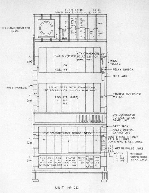
Shelf E:
This shelf serves the same function as Shelf E on the C unit, (which this unit replaced). Again Multi-metering sets took up the first three postions on the shelf, followed by two delayed alarm sets and the test number set. This was followed by a new relay set that controlled the PG alarm and 30 second pulses that were required by the exchange. The PG alarm was in conjunction with the contact milliamperemeter at the top of the rack. When a certain amount of group selectors were siezed, but not stepped, the PG (permanent glow) lamp would illuminate. This lamp was wired to a common PG lamp feed, which came via this milliammeter. When a certain amount of selectors were held (differing sizes of exchanges were allowed different numbers of selectors to be held) the needle would rise, and the contacts would be made, raising the PG alarm.
The last relay-set is teh alarm extension set.
Shelf D:
This accomodates 8 non-parent junction relay sets, and if these were AGS 192 they used the uniselctors mounted on shelf C.
Shelf B & A:
These shelves accomodate junction relay sets.